Control models
The battery model contains a Control sub-model, see the overall model structure description. The Control model determine the control values and type.
At a given time, there are in general two control types:
Total current
Voltage
Given a control type, the control value can change in time. For the most standard control types, the json interface can be used. We plan to include there more control models. Below, we give some short explanations on how a control model can be implemented.
Json input control interface
The most standard controls can be called from BattMo using the json interface:
Constant Current Discharge (CCDischarge)
Constant Current Charge (CCCharge)
Constant Current Constant Voltage (CCCV)
The parameters for each of the model are described in the json schema ControlModel.schema.json. Let us review them by looking at examples. For all controls, we have
a given CRate. The property controlPolicy is used to set the control model.
Constant Current Discharge
Before the simulation starts, the capacity of the battery is computed. The battery capacity value is used to compute the
given input current from the CRate value. For a constant current discharge, we have a lower cutoff voltage where the
simulation stops. The parameter useCVswitch can be used if we want to continue the simulation until a given
fixed time, by switching to voltage control. At the start of the simulation, strong non-linearities in the equations may
create difficulties to reach the activation potential. For this reason, there is the possibility to use a rampup time
where the current is gradually increased from zero to the targeted given input current.
 "Control": {
  "controlPolicy": "CCDischarge",
  "rampupTime": 0.1,
  "CRate": 1,
  "lowerCutoffVoltage": 2.4
}
For the dataset given here, we obtain the following result.
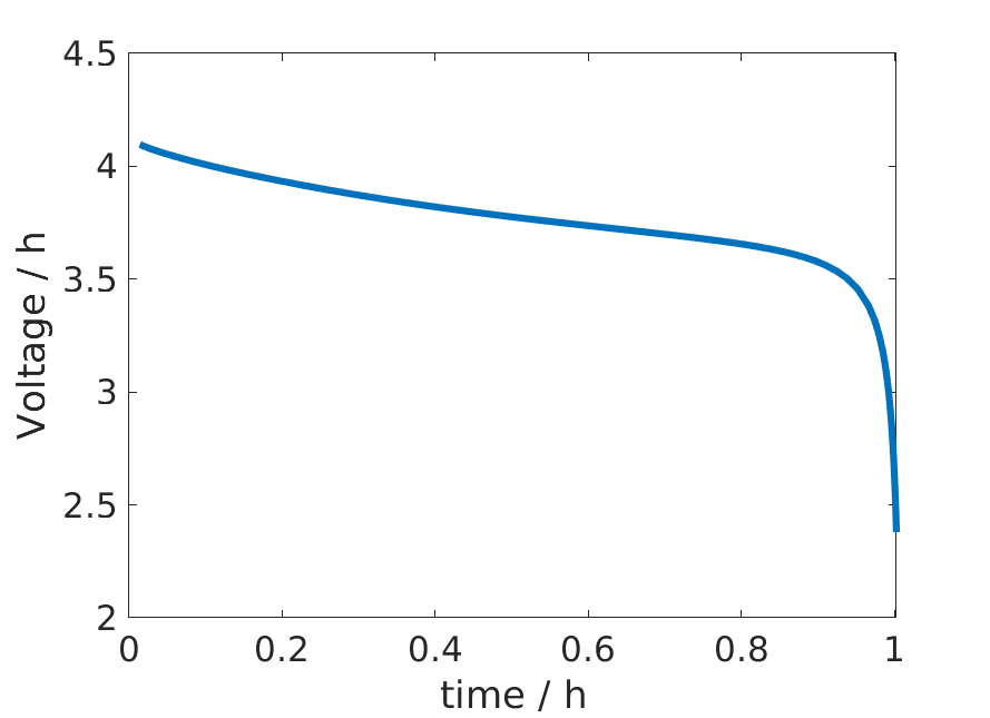
Constant Current Discharge control
Constant Current Charge
In the same way as the discharge case, the capacity of the battery is computed first to set the given input current from the CRate. When the upper cuttoff voltage limit is reached, the control type is switched to voltage control. Also in this case, we can include a rampup time. As an example,
 "Control": {
  "controlPolicy": "CCCharge",
  "rampupTime": 0.1,
  "CRate": 1,
  "upperCutoffVoltage": 4.1,
}
For the dataset given here, we obtain the following result.
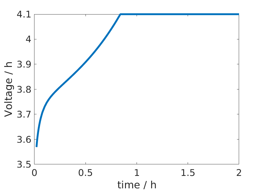
Constant Current Charge control
Constant Current Constant Charge
An example of input is
 "Control": {
  "controlPolicy": "CCCV",
  "CRate": 1,
  "initialControl": "discharging",
  "numberOfCycles": 2,
  "lowerCutoffVoltage": 2.4,
  "upperCutoffVoltage": 4.1,
  "dIdtLimit": 1e-5,
  "dEdtLimit": 1e-5
},
The control type and value are set following the following procedure. In the case above, we start by discharging
We use a constant discharge current computed from the capacity and the given CRate. We keep this value until the lower cutoff voltage value is reached. Then, we switch to step 2.
The control is set to zero. At each time step we compute the time derivative of the voltage \(\frac{dE}{dt}\). When this value reach the limit given by
dEdtLimit. We start the charge step 3.We use a constant charge current. The value is the same as in step 1, with opposite sign. We keep this current until the lower cutoff voltage limit is reached. Then we switch to constant voltage control step 4.
We use a constant voltage given by the cutoff value and monitor the current derivative \(\frac{dI}{dt}\). When this value is lower than
dIdtLimit, we start again the discharge by going to step 1.
We iterate this process for the given number of cycles. For the dataset given here, we obtain the following result.
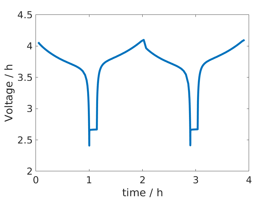
CCCV control
The script used to generate the figures is available here.
Control model description
Beside json input, the function simulateScheduleAD is used to run a simulation. It requires
A model, which knows how to setup and solve the governing equations of our problem,
An initial state,
A schedule, which provides the time stepping and can also contain setup for control
The schedule contains two fields
control: It is a struct array containing fields that the model knows how to process. Typically, this will be the fields such as src for input current.step: It contains two arrays of equal size namedvalandcontrol. Control is a index into theschedule.controlarray, indicating which control is to be used for the timestep.schedule.step.valis the timestep used for that control step.
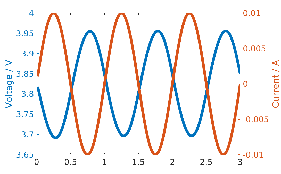
Let us set up a control with a given current control source function. In this case, we choose a sinusoidal current control.
dt = 1*second;
T  = 3*minute;
N  = T/dt;

step.val = dt*ones(N, 1);
step.control = ones(N, 1);

period = 1*minute;
control.src = @(time) (1e-2*ampere*sin(2*pi*time/period));
control.CC = true;

schedule.step = step;
schedule.control = control;
We have to setup a model and an initial state. We use the function setupModelFromJson to setup the model from
a given json input. We load the sample input function we have used before, see source
here. We replace the Control field with a structure with
a controlPolicy given by a current control (CC). We change the initial state of charge value (SOC) to
0.5 so that we do not hit the upper current voltage value (the SOC given in the sample json is 0.99).
jsonstruct = parseBattmoJson('Examples/jsondatafiles/sample_input.json');

jsonstruct.Control = [];
jsonstruct.Control.controlPolicy = 'CC';

jsonstruct.SOC = 0.5;

model = setupModelFromJson(jsonstruct);
We use the default state initialisation method given by the method setupInitialState in the Battery model.
initstate = model.setupInitialState(jsonstruct);
Now, we can run the simulation for the given schedule, model and initial state using simulateScheduleAD
[~, states] = simulateScheduleAD(initstate, model, schedule);
The complete source can be found here exampleControl_doc.